#gpiozero library
Wednesday, February 12, 2025
Thursday, January 30, 2025
fuzzy search
Below are from answers get from Deepseek
### **How Fuzzy Search Works**
Fuzzy search is designed to find strings that approximately match a given query, even if the query contains typos, misspellings, or incomplete words. The key idea is to rank potential matches based on how closely they align with the query.
#### Key Concepts:
1. **Subsequence Matching**:
- Fuzzy search looks for whether the characters in the query appear in the target string **in the same order**, but not necessarily consecutively.
- For example, the query `"leaders"` matches `"leadership skills"` because the letters `l`, `e`, `a`, `d`, `e`, `r`, `s` appear in order within the target string.
2. **Scoring**:
- Matches are ranked based on how closely they align with the query. Factors like:
- **Proximity of characters**: Characters that appear closer together in the target string are preferred.
- **Completeness**: Matches that include more of the query characters are ranked higher.
3. **Efficiency**:
- Fuzzy search algorithms are optimized to quickly filter and rank potential matches, even in large datasets.
---
### **How FuzzyFinder Implements Fuzzy Search**
FuzzyFinder uses a simple yet effective approach to implement fuzzy search. Here’s a high-level overview of how it works:
#### Algorithm Steps:
1. **Preprocessing**:
- Convert both the query and the target strings to lowercase (to make the search case-insensitive).
2. **Subsequence Matching**:
- For each target string, check if the characters in the query appear in the same order within the target string.
- Example:
- Query: `"leaders"`
- Target: `"leadership skills"`
- Check if `l`, `e`, `a`, `d`, `e`, `r`, `s` appear in order in `"leadership skills"`.
3. **Scoring**:
- Assign a score to each match based on:
- **Character proximity**: Characters that appear closer together in the target string are preferred.
- **Match completeness**: Matches that include more of the query characters are ranked higher.
4. **Ranking**:
- Sort the matches based on their scores and return the results.
---
### **Example Implementation of Fuzzy Search**
If you wanted to implement a simple version of fuzzy search yourself, here’s how you could do it in Python:
#### Code:
```python
def fuzzy_search(query, choices):
query = query.lower()
matches = []
for choice in choices:
choice_lower = choice.lower()
i = 0 # Index for query
j = 0 # Index for choice
score = 0
# Check if query characters appear in order in the choice
while i < len(query) and j < len(choice_lower):
if query[i] == choice_lower[j]:
i += 1
score += 1 # Increase score for each matching character
j += 1
# If all query characters were found in order, add to matches
if i == len(query):
matches.append((choice, score))
# Sort matches by score (higher scores first)
matches.sort(key=lambda x: x[1], reverse=True)
return [match[0] for match in matches]
# Example usage
terms = [
"team leaders",
"project leaders",
"leadership skills",
"manager",
"ceo",
"director",
"lead developer",
"head of department",
"lead engineer",
"leadership training"
]
query = "leaders"
matches = fuzzy_search(query, terms)
print("Fuzzy matches for 'leaders':", matches)
```
#### Output:
```
Fuzzy matches for 'leaders': ['team leaders', 'project leaders', 'leadership skills', 'leadership training']
```
---
### **Why FuzzyFinder is Efficient**
FuzzyFinder is optimized for performance. It avoids complex calculations (like Levenshtein distance) and instead focuses on **subsequence matching** and **scoring**, which makes it fast and suitable for real-time applications.
---
### **Comparison with Other Algorithms**
1. **Levenshtein Distance**:
- Measures the number of edits (insertions, deletions, substitutions) required to transform one string into another.
- More accurate but computationally expensive for large datasets.
2. **FuzzyWuzzy**:
- Uses Levenshtein distance and provides similarity scores.
- Slower than FuzzyFinder but more precise.
3. **Regular Expressions**:
- Can be used for pattern matching but doesn’t handle typos or approximate matches.
---
### **When to Use FuzzyFinder**
- When you need **fast, approximate matching** for large datasets.
- When you want a lightweight solution without heavy dependencies.
- When you don’t need the precision of Levenshtein distance.
---
### **Conclusion**
FuzzyFinder’s algorithm is not overly complicated—it relies on **subsequence matching** and **scoring** to efficiently find approximate matches. If you’re curious, you can even implement a basic version yourself (as shown above) to understand how it works under the hood.
If you’d like to dive deeper into the implementation or explore more advanced fuzzy search techniques, let me know! 😊
Sunday, April 28, 2024
C Programming
Header Files and Includes
Preprocessing Macros
I found this usage of defining empty macros in pico sdk, and it's sometimes useful:
#define _REG_(x)
_REG_(SIO_GPIO_OE_SET_OFFSET)
Thursday, February 8, 2024
SVN Quick Reference
this is a short summary for my reference based on the great official tutorial at:
Basic Work Cycle (red-bean.com)
Check out a working copy from a repository
$ svn checkout -r 1234 url://repository/path
Update Your Working Copy
%svn update #this will download latest version file from repository to local working copy
#NOTE: will overwrite any local changes not commited?
%svn up -r 1234 #Checkout a specific revision from SVN
Make Your Changes
%svn add <file>
%svn delete <file>
%svn copy <file>
%svn move <file>
%svn mkdir <dir>
Changing the Repository Without a Working Copy
#not interested in this at this stage
Review Your Changes
%svn status #only show the local files different from local checkouted version in repository
#Note: even without internet work, svn can still show the changes, this is because svn keeps an origianl file in local.
%svn status stuff/fish.c #If you pass a specific path to svn status, you get information about that item alone
%svn status -v #verbose options, shows status of every local file
%svn status -u -v #-u options means -update, it shows also show you if any files has newer version in repository than you local version. outdated version and changed files will need resolve
$svn diff #difference details of locally changes files
%svn diff --old <file0> --new <file1> #like diff command, shows differences between two files
most common codes that svn status displays:
? item #The file, directory, or symbolic link item is not under version control.
A item #The file, directory, or symbolic link item has been scheduled for addition into the repository.
C item #The file item is in a state of conflict. That is, changes received from the server during an update overlap with local changes that you have in your working copy (and weren't resolved during the update). You must resolve this conflict before committing your changes to the repository.
D item #The file, directory, or symbolic link item has been scheduled for deletion from the repository.
M item #The contents of the file item have been modified.
! item #Item is missing (e.g., you moved or deleted it without using svn). This also indicates that a directory is incomplete (a checkout or update was interrupted).
#Note: advanced ussage of patch command from svn1.7 a future topic to study.
Fix Your Mistakes
%svn revert <file> #revert any changes you made to local copy of files
#Note: But note that svn revert can undo any scheduled operation—for example, you might decide that you don't want to add a new file after all
Resolve Any Conflicts
#TODO
Commit Your Changes
%svn commit -m "Corrected number of cheese slices."
Examining History
%svn diff -r 3 rules.txt #If a single --revision (-r) number is passed, your working copy is compared to the specified revision in the repository
%svn diff -r 2:3 rules.txt #If two revision numbers, separated by a colon, are passed via --revision (-r), the two revisions are directly compared:
%svn diff -c 3 rules.txt #A more convenient way of comparing one revision to the previous revision is to use the --change (-c) option:
%svn diff -r{2024-10-02} -r{2024-10-06} --summarize #list changed filenames between two dates
%svn log <file> #history message of a file
%svn log -q <file> #-q quiet, only show file name
%svn diff --summarize -r42:41 #just pirnt the filenames that has changes between 2 commitsCheckout a Specific Version of files
svn checkout -r 100 https://example.com/svn/repo/trunk/folder [/path/to/workspace/folder]
svn checkout -r {2023-01-01} https://example.com/svn/repo/trunk/folder [/path/to/workspace/folder]
Sometimes You Just Need to Clean Up
#you can just delete the local working copy without the need to notify server
#before removing local working copy, remommend to run svn status just to make sure you dont have anything changes that you want to keep
Saturday, January 13, 2024
PCIe Study Notes
Chapter 1: Background
Nice References
terminologies: PCIE常用缩写及含义_pcie elbi-CSDN博客
PCI
#TO Study Further: Reflected-Wave Signaling and the impact on number of max electrical load. higher frequencies -> less fewer load allowed on the bus. PCI frequency cannot faster than 66MHz.
Transaction Models: Programmed I/O, DMA, Peer-to-Peer.
PCI is a Shared Bus Architecture; PCI arbitration algorithm must be "fair" and not starve any device for access.
PCI Inefficiencies: 1) Retry: init->target not ready for >16T -> target retry initiator (STOP#); 2) Discconnect: init -> target transfer some data, then not ready for >8T -> target signal disconnect to initiator (STOP#)
Address Space Map: memory Map, IO Map, PCI Configuration Space( 256B per function)
PCI Configuration Header: Type0: non-bridge (6BARs), Type1: bridge (2 BARs)
PCI-X
PCI-X transfer efficiency ~85% vs PCI ~50%~60%
PCI-X Split-Transaction Model: Reqeust-Completer. Completer will memorize transaction (address, transaction type, count, requester ID) and signal a split response.
PCI-X add Attribute stage
PCI-X add MSI(Message Signaled Interrupt): eliminate the need to share interrupts accross multiple deivces. memory write trans, to pre-defined address range, data is interrupt vector of that device. cpu avoids the overhead of finding which device generated the interrupt. no sideband pins are needed.
PCI-X uses common or distributted clock: 1. signal skew; 2) clock skew between multiple devices; 3) flight time budget
PCI-X 2.0 is point-to-point design, instead of shared bus arch.
PCI-X 2.0 uses Source-synchronous clocking model
Chapter 2: PCIe Architecture Overview
PCIe serial data transmission.
Transaction Layer
Full Duplex
A Transaction is defined as the combination of a Request packet that a delivers a command to a targeted device, together with any completion packets the target sends back in reply.
posted transactions and non-posted transactions:
Memory Read -> Non-Posted
Memory Write -> Posted
Memory Read Lock -> Non-Posted
IO Read -> Non-Posted
IO Write -> Non-Posted
Configuration Read (Type 0 and Type 1) -> Non-Posted
Configuration Write (Type0 and Type 1) -> Non-Posted
Message -> Posted
Non-posted write (IO write and Cfg write) and Memory Read Lock can only come from the processor.
TLP (Transaction Layer Packet)
QoS: Virtual Channel Buffer
Data Link Lyaer
Layer main function:
TLP error correction: Ack/Nack causing LP retry
flow control
some Link power managment
DLLP fixed length: 8B
DLLP (Data Link Layer Packets) only transferred between Data Link Layers of the two neighboring devices on a Link, and not routed anywhere else.
Ack DLLP has the last good TLP sequence Number, and the transmitter flushes all the TLPs that wer send before the acked sequence number. the sequence number is generated by Data Link Layer, so it's always in order!
Nack DLLP: Receiver truturns a Nack to the transmitter when it detectrs a TLP error and drops this TLP. the transmitter then will replay all unacknowledged TLPs.
Error Check and Retry: Replay Buffer
Flow Control:
#TODO: hwen in NAK of MRd, while completer resend the CplD, there maybe new MWr from other requester, so the old CplD data may not be up to date. Is this expected?
Physical Layer
#TODO: transmission order on the physical line.
Logical Part
#TODO: ppm long term will cause overflow, how does ethernet and PCIe resolve this?
Elastic Buffer
Byte-Stripped?
Link Training and Initialization: several things are checked or established to ensure proper and optimal operation, such as:
Link width
Link data rate
Lane erversal - Lanes connected in reverse order
Polarity inversion - Lane polarity connected backward
Bit lock per Lane - Recovering the transmitter clock
Symbol lock per Lane - Findding a recognizable position in the bit-stream
Lane-to-Lane de-skew within a multi-Lane Link
Electriclal Part
Ordered Sets: always 4B. always terminate at the neighboring deivecs and are not routed through the PCIe fabric.
used in 1) link training; 2) ppe compensation; 3) enter/exit of low power state on the link
Chapter 3: Configuration Overview
Enumeration
PCIe Buses: up to 256 Bus; Initial Bus 0 is tpoically assigned by HW to RC. Bus 0 consists of a Virtual PCI bus with integrated endpoints and Virtual PCI-to-PCI Bridges(P2P), which are hard-coded with a Device No. and Function No.
PCIe Devices: 32 devices per bus; PCIe point-to-point link means that device will always be Device 0. Deach Device must implement Function 0.
PCIe Functions: Functions do not need to be implemented sequenctially. SW must check every one of the 8 functions to decide which are present.
Errors should not normally be reported during enumeration.(the enumeration sw could fail since it's typically writtent o execute before the OS or other error handling SW is available.
Device not present: SW get Vendor ID of FFFFh, reserved for "device not present"
#TODO: enumeration started after 100ms+link training after reset, how to do it in DV simulation?
#TODO: what will enum sw do if there is no EP attached to a pci-pci bridge? #multi-root system: what if rc assign start bus number 64 to rc, but later find that the total buses are more then 265-64? is this an error? It is important to remember that each port on a switch is aBridge, and thus has its own configuration space with a Type 1 Header. In reality, each port (each P2P Bridge) has its own Type 1 Header and performs the same two checks on TLPs when they are seen by that port.
#TODO: enumeration started after 100ms+link training after reset, how to do it in DV simulation?
#TODO: what will enum sw do if there is no EP attached to a pci-pci bridge?
Chapter 4: Address Space & Transaction Routing
Confugration
Confugartion Space Total 4KB/function:
1. (256B/64DW) PCI-compatible spece access by legacy PCI software or PCIe enhanced configuration access mechanism: 64B for Configuration Headers (Type0/Type 1); 192B for Function-Specific Configuration Header Space.
2. (960DW) PCIe Extended space is only accessible by PCIe Ehanhanced Configuration Access Mechanism: for optional extended capability registers: ...
Enhanced Configuration Mechanism memory-mapped Address Range:
A[63:28]: upper bits of the 256MB-aligned base address of the address range allocated for PCIe enhanced configuration mechanism.
BAR only 32bits, how to handle >4GB address? Mem address 64-bit decoding uses 2 BARs.
BARs are used for decide which system address can be used to access the PCIe functions' internal locations.
BARs device has 6, but not all needs to be implemented, harded coded value of all 0 means it's not implemented.
All BARs must be evaluated sequentially.
Where is the BAR? it's inside each function?
#TODO: how base/limit registers to mean unused registers? e.g. if does not use IO address space, how to cfg IO base/limit register?
Base/Limit only needed in type 1 Bridge ports.
TLP Routing
Routing based on TLP header FMT/Type fields.
TLP:
MRd
MRdLk
MWr
IORd
IOWr
CfgRd0
CfgWr0
CfgRd1
CfgWr1
Msg
MsgD
Cpl
CplD
CplLk
CplDLk
FetchAdd
Swap
CAS
LPrfx
EPrfx
Address routing: MRd, MRdLk, MWr, AtomicOp, IORd, IOWr, Msg/MsgD
ID routing: CfgRd/Wr, Cpl/CplD, CplLk/CplDLk
Implicit routing: Msg/MsgD, for messages to mimic side-band signals.
Saturday, August 19, 2023
TCP/IP Study Notes
TCP/IP segmentation and fragmentation:
reference link: 【计算机网络】区分tcp分段和ip分片 - JoyoHub
Virtualbox Settings Reference
Networking Settings
to record issues when setting up different network options for my guest linux virtual machine.
refernce link: 【计算机网络】:一次性理清Virtualbox虚拟机网络模型 - JoyoHub
reference link: https://www.nakivo.com/blog/virtualbox-network-setting-guide/
1. issues when usign Bridged Adapter mode.
cannot get ipv4 address
set to NAT mode first, and get ip address by checking ifconfig
then switch to Bridged Adapter mode, and very importantly, choose the correct NIC (if you are using wifi, choose the wireleass NIC! in my case default is ehterent NIC, and i must change it to my wifi NIC), then check the ip address now using ifconfig. it works for me!
Extension Pack Installation
1. download and install
2. In order for VirtualBox to have access to the USB subsystem, the user running VirtualBox must belong to the vboxuser group. To do this:
% sudo usermod -aG vboxusers <your-username>
Note: if there is no vboxusers group, you need to first add it:
%sudo groupadd vboxusers
Enable USB
1. you need to first add the devices that you want the guest os to access in the hostos virtualbox settings.
Monday, June 26, 2023
Traffic Management
Rate Limiting
Refer: https://hansliu.com/posts/2020/11/what-is-token-bucket-and-leaky-bucket-algorithms.html
1. Token bucket
- Rate Limiting: produce rate of token
- Bucket Sizes: number of token
- Token Check: if token valid, process data

2. leaky bucket
- Rate Limiting: consume rate of data
- Bucket Sizes: number of data


Queueing QoS
WFQ, FQ, WRR
http://what-when-how.com/qos-enabled-networks/queuing-and-scheduling-qos-enabled-networks-part-1/
Monday, January 11, 2021
Systemverilog Assertion Notes
refer to: Dulos SVA tutorial
I) Immediate Assertions
Guideline: Avoid using immediate assertions
assert (A == B); // Asserts that A equals B; if not, an error is generated
assert (A == B) $display ("OK. A equals B");
assert (A == B) $display ("OK. A equals B"); else $error("It's gone wrong");
assert (A == B) else $error("It's gone wrong");
The failure of an assertion has a severity associated with it: $fatal, $error (the default severity) and $warning. In addition, the system task $info indicates that the assertion failure carries no specific severity.
Igt10: assert (I > 10) else $warning("I is less than or equal to 10");
The pass and fail statements can be any legal SystemVerilog procedural statement.
AeqB: assert (a === b) else begin error_count++; $error("A should equal B"); end
II) Concurrent Assertions
Guideline: Use concurrent assertions
Guideline: Use long, descriptive labels to your assertions code, (a) documents the assertions, and (b) accelerates debugging using waveform displays.
Guideline: Use label names that start with "ERR" or "ERROR" and then include a short sentence to describe what is wrong if that assertion is failing.
Properties are built using sequences. For example,
assert property (@(posedge Clock) Req |-> ##[1:2] Ack);
where Req is a simple sequence (it’s just a boolean expression) and ##[1:2] Ack is a more complex sequence expression, meaning that Ack is true on the next clock, or on the one following (or both). |-> is the implication operator, so this assertion checks that whenever Req is asserted, Ack must be asserted on the next clock, or the following clock.
Concurrent assertions like these are checked throughout simulation. They usually appear outside any initial or always blocks in modules, interfaces and programs. (Concurrent assertions may also be used as statements in initial or always blocks. A concurrent assertion in an initial block is only tested on the first clock tick.)
III) Implications
Guideline: Use |-> ##1 implications and not |=> implications.
|-> tests for a valid consequenct expression in the same cycle.
|=> tests for a valid consequenct expression in the next cycle.
IV) Properties and Sequences
Properties and Sequences In these examples we have been using, the properties being asserted are specified in the assert property statements themselves. Properties may also be declared separately, for example:
property not_read_and_write; not (Read && Write); endproperty assert property (not_read_and_write);
Complex properties are often built using sequences. Sequences, too, may be declared separately:
sequence request Req; endsequence sequence acknowledge ##[1:2] Ack; endsequence property handshake; @(posedge Clock) request |-> acknowledge; endproperty assert property (handshake);
V) Assertion Clocking
The clock for a property can be specified in several ways:
Explicitly specified in a sequence:
sequence s; @(posedge clk) a ##1 b; endsequence property p; a |-> s; endproperty assert property (p);
Explicitly specified in the property:
property p; @(posedge clk) a ##1 b; endproperty assert property (p);
Explicitly specified in the concurrent assertion: assert property (@(posedge clk) a ##1 b);
Inferred from a procedural block:
property p; a ##1 b; endproperty always @(posedge clk) assert property (p);
From a clocking block (see the Clocking Blocks tutorial):
clocking cb @(posedge clk); property p; a ##1 b; endproperty endclocking assert property (cb.p);
From a default clock (see the Clocking Blocks tutorial):
default clocking cb;
VI) Handling Asynchronous Resets
In the following example, the disable iff clause allows an asynchronous reset to be specified.
property p1;
@(posedge clk) disable iff (Reset) not b ##1 c;
endproperty
assert property (p1);
The not negates the result of the sequence following it. So, this assertion means that if Reset becomes true at any time during the evaluation of the sequence, then the attempt for p1 is a success. Otherwise, the sequence b ##1 c must never evaluate to true.
VII) Sequences
A sequence is a list of boolean expressions in a linear order of increasing time. The sequence is true over time if the boolean expressions are true at the specific clock ticks. The expressions used in sequences are interpreted in the same way as the condition of a procedural ifstatement. Here are some simple examples of sequences.
The ## operator delays execution by the specified number of clocking events, or clock cycles.
a ##1 b // a must be true on the current clock tick // and b on the next clock tick
a ##N b // Check b on the Nth clock tick after a
a ##[1:4] b // a must be true on the current clock tick and b // on some clock tick between the first and fourth // after the current clock tick
The * operator is used to specify a consecutive repetition of the left-hand side operand.
a ##1 b [*3] ##1 c // Equiv. to a ##1 b ##1 b ##1 b ##1 c
(a ##2 b) [*2] // Equiv. to (a ##2 b ##1 a ##2 b)
(a ##2 b)[*1:3] // Equiv. to (a ##2 b) // or (a ##2 b ##1 a ##2 b) // or (a ##2 b ##1 a ##2 b ##1 a ##2 b)
The $ operator can be used to extend a time window to a finite, but unbounded range.
a ##1 b [*1:$] ##1 c // E.g. a b b b b c
The [-> or goto repetition operator specifies a non-consecutive sequence.
a ##1 b[->1:3] ##1 c // E.g. a !b b b !b !b b c
This means a is followed by any number of clocks where c is false, and b is true between 1 and three times, the last time being the clock before c is true.
The [= or non-consecutive repetition operator is similar to goto repetition, but the expression (b in this example) need not be true in the clock cycle before c is true.
a ##1 b [=1:3] ##1 c // E.g. a !b b b !b !b b !b !b c
VIII) Combining Sequences
There are several operators that can be used with sequences:
The binary operator and is used when both operand expressions are expected to succeed, but the end times of the operand expressions can be different. The end time of the end operation is the end time of the sequence that terminates last. A sequence succeeds (i.e. is true over time) if the boolean expressions containing it are true at the specific clock ticks.
s1 and s2 // Succeeds if s1 and s2 succeed. The end time is the // end time of the sequence that terminates last If s1 and s2 are sampled booleans and not sequences, the expression above succeeds if both s1 and s2 are evaluated to be true.
The binary operator intersect is used when both operand expressions are expected to succeed, and the end times of the operand expressions must be the same.
s1 intersect s2 // Succeeds if s1 and s2 succeed and if end time of s1 is // the same with the end time of s2
The operator or is used when at least one of the two operand sequences is expected to match. The sequence matches whenever at least one of the operands is evaluated to true.
s1 or s2 // Succeeds whenever at least one of two operands s1 // and s2 is evaluated to true
The first_match operator matches only the first match of possibly multiple matches for an evaluation attempt of a sequence expression. This allows all subsequent matches to be discarded from consideration. In this example:
sequence fms;
first_match(s1 ##[1:2] s2);
endsequence
whichever of the (s1 ##1 s2) and (s1 ##2 s2) matches first becomes the result of sequence fms.
The throughout construct is an abbreviation for writing:
(Expression) [*0:$] intersect SequenceExpr
i.e. Expression throughout SequenceExpr means that Expression must evaluate true at every clock tick during the evaluation of SequenceExpr.
The within construct is an abbreviation for writing:
(1[*0:$] ##1 SeqExpr1 ##1 1[*0:$]) intersect SeqExpr2
i.e. SequenceExpr1 within SequenceExpr2 means that SeqExpr1 must occur at least once entirely within SeqExpr2 (both start and end points of SeqExpr1 must be between the start and the end point of SeqExpr2).
IX) Variables in Sequences and Properties
Variables can be used in sequences and properties. A common use for this occurs in pipelines:
`define true 1
property p_pipe;
logic v;
@(posedge clk) (`true,v=DataIn) ##5 (DataOut === v);
endproperty
In this example, the variable v is assigned the value of DataIn unconditionally on each clock. Five clocks later, DataOut is expected to equal the assigned value. Each invocation of the property (here there is one invocation on every clock) has its own copy of v. Notice the syntax: the assignment to v is separated from a sequence expression by a comma, and the sequence expression and variable assignment are enclosed in parentheses.
X) Coverage Statements
In order to monitor sequences and other behavioural aspects of a design for functional coverage, cover property statements can be used. The syntax of these is the same as that of assert property. The simulator keeps a count of the number of times the property in the cover property statement holds or fails. This can be used to determine whether or not certain aspects of the designs functionality have been exercised.
module Amod2(input bit clk);
bit X, Y;
sequence s1; @(posedge clk) X ##1 Y; endsequence
CovLavel: cover property (s1);
...
endmodule
SystemVerilog also includes covergroup statements for specifying functional coverage. These are introduced in the Constrained-Random Verification Tutorial.
XI) Assertion System Functions
SystemVerilog provides a number of system functions, which can be used in assertions. $rose, $fell and $stable indicate whether or not the value of an expression has changed between two adjacent clock ticks. For example,
assert property (@(posedge clk) $rose(in) |=> detect);
asserts that if in changes from 0 to 1 between one rising clock and the next, detect must be 1 on the following clock. This assertion,
assert property (@(posedge clk) enable == 0 |=> $stable(data));
states that data shouldn’t change whilst enable is 0.
The system function $past returns the value of an expression in a previous clock cycle. For example,
assert property (@(posedge clk) disable iff (reset) enable |=> q == $past(q+1));
states that q increments, provided reset is low and enable is high. Note that the argument to $past may be an expression, as shown above.
The system functions $onehot and $onehot0 are used for checking one-hot encoded signals. $onehot(expr) returns true if exactly one bit of expr is high; $onehot0(expr) returns true if at most one bit of expr is high.
assert property (@(posedge clk) $onehot(state));
There are other system functions.
XII) Binding
Guideline: bindfiles, use them!
Guideline: Use the bind command style that binds to all DUT modules, not the bind style that only binds to specified instances.
a) bind to all instances of a module
bind fifo1 fifo1_asserts p1 (.*);
b) bind to specific DUT instance with or without using the module name
Guideline: do not use these styles.
c) bindfiles for parameterized modles
d)bindfiles with .* port connections
Wednesday, November 4, 2020
I2C IIC Tutorial
1. The Protocol
Resolving address conflicts: https://embeddedartistry.com/blog/2021/08/02/resolving-i2c-address-conflicts/
1.1 Controller control the bus, in particular controls the SCL clock line to control the speed of transmissions
Peripherals cannot control the bus directly.
Pull-up resistors for pull up line to high. Resistor selection varies with devices on the bus, but a good rule of thumb is to start with 4.7kΩ resistor and adjust down if necessary. I2C is a fairly robust protocol, and can be used with short runs of wire (2-3m). For long runs, or systems with lots of devices, smaller resistors are better.
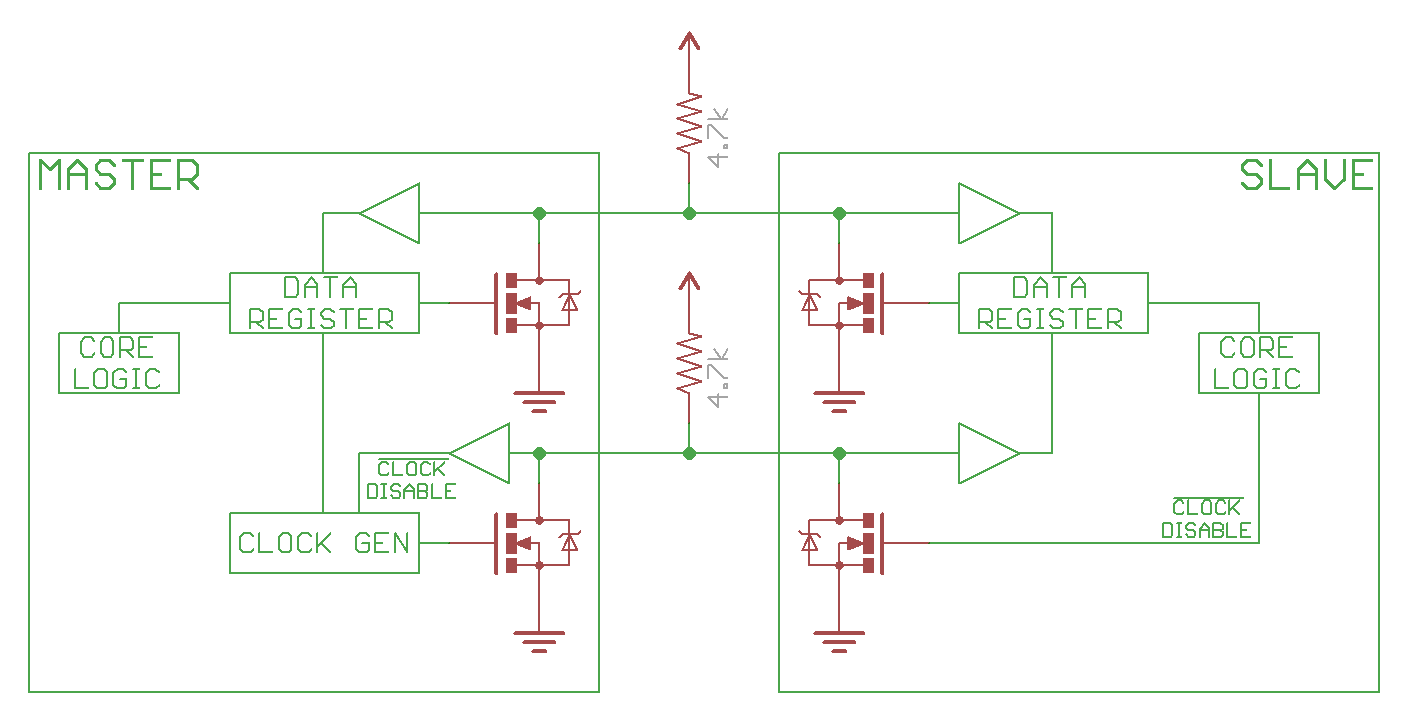
1.2 controller (master), peripheral(slave) use open drain drivers, to pull the line low, turn on the FET, to have the line high, just disconnect the FET (open drain), and the pull up resistor will pull line to high.
below image is from Sparkfun tutorials (sparkfun i2c tutorial)
1.3 speed
100kHz (Standard Mode)
400kHz (Fast Mode, Fm)
1MHz(Fast Mode Plus, Fm+)
3.4MHz(High-Speed Mode, Hs)
5MHz(Ultra Fast Mode, Ufm) - completely different bus, no pullup resistor, not common at all yet.
1.4 Start/Stop conditions
The only time the data line can change when the clock line is high is during the Start and Stop conditions.
Start marks the beginning of I2C transaction, bus must be idle, both SDA and SCL must be high. SDA goes low first, followed shortly by SCL.
Stop marks the end of I2C transaction. bus must be active, both SDA and SCL must be low. SCL goes high first, followed by SDA.
1.5 Sending Address and Data
Controller must send an address for every transaction. the address is to identify the peripheral that the controller is trying to talk to.
The address is 7bits, with one extra bit for Read(1)/Write(0).
Data is sampled at rising clock edge.
During regular transmissions, the the Controllers/Peripherals must wait until the clock line is low before changing the data line to set for the next bit to transmit.
data is always sent in unit of 8bits (1 Byte), transmitted most significant bit (MSB) first.
1.6. ACK/NACK
Each 8bits data/address must be followed by a ACK/NACK bit.
The side receiving the data needs to drive the ACK/NACK bit.
ACK bit is 0, NACK is 1.
when the controller is sending address, the NACK is set if no peripherals match that address.
when controller is writing, the peripheral send ACK if
when controller is reading, the controller send ACK if it wants to continue read data, and NACK to notify the peripheral to end the transaction.
1.7 Arbitration
arbitraion is automatic. Each controller is monitoring the line state, and the losing side will know it lost the arbitration once it trying to send a 1 but the line state is 1. It's non destructive, in that the winning side does not even know that there is a arbitration happened! that's the beauty of
1.8 Repeated Start Condition
sometimes controller end a transaction by sending another Start condition instead of a Stop condition. this is called Repeated Start Condition. this happens when controller wants to start a new transaction without letting go of the bus. Common example is when controller wants to switch from writing data to a peripheral to reading data from a peripheral.
1.9 10-bit Addressing
a specific 7-bit address value (7'b11110xx) denotes that the I2C is using 10-bit extended addressing scheme. the first two bits of the 10-bit address is in the last 2 bits of the 7-bit address value, and the remaining 8bits is sent as the following data byte. the read immediately after write is bit different, refer to Fig. 15 in the I2C spec.
1.10 Clock Streching
2. Arduino Software Application
Sunday, August 2, 2020
PRBS using linear feedback shift register implemented in Python
#! /usr/bin/env python3
def prbs_gen(msg, bitwidth, poly, seed, pam_mode):
print(msg, 'poly=', poly, 'seed=', seed, ':')
mask = ~((~0)<<bitwidth);
lfsr = seed
period = 0
bit = 0
while period < 32:
for x in range(pam_mode+1):
bit <<= 1
bit |= cal_parity(mask&(poly&lfsr))
lfsr = mask & ( (lfsr <<1) | (bit&1) )
if pam_mode == 1 :
bit &= 0x3
gray_code_dict = {0:0, 1:1, 2:3, 3:2}
bit = gray_code_dict[bit];
else:
bit &=0x1
if period%4 == 0:
print(' ', end='')
print(bit, end='')
period += 1
print('\n')
return period
def cal_parity(value):
value ^= (value>>16)
value ^= (value>>8)
value ^= (value>>4)
value &= 0xf
return (0x6996>>value)&0x1
#below are example unction calls for some prbs types:
prbs_gen('LT136/LT162 prbs13Q 0', 13, 0x1803, 0x1aa0, 1);
prbs_gen('LT136/LT162 prbs13Q 1', 13, 0x1046, 0x105c, 1);
prbs_gen('LT136/LT162 prbs13Q 2', 13, 0x108a, 0x0689, 1);
prbs_gen('LT136/LT162 prbs13Q 3', 13, 0x1112, 0x0822, 1);
prbs_gen('LT93 prbs11 0', 11, 0x630, 0x3f5, 0);
prbs_gen('LT93 prbs11 1', 11, 0x530, 0x513, 0);
prbs_gen('LT93 prbs11 2', 11, 0x4a8, 0x5a7, 0);
prbs_gen('LT93 prbs11 3', 11, 0x468, 0x36f, 0);
prbs_gen('LT72 prbs11 0', 11, 0x503, 0x36f, 0);
Friday, May 8, 2020
Photoshop
photoshop
Affinity Photo with pen tablet:
Ctrl+Alt(option)+drag: left/right for brush size, up/down for hardness
Spacebar+Cmd+drap: left/right zoom out/in
Cmd+0: zoom to fit window
B: brush tool
J: healing brush
J: spot healing brush
S: clone stamp
H: hand tool(view)
New Layer: Shift+Cmd+N
Affinity Photo with pen tablet:
Ctrl+Alt(option)+drag: left/right for brush size, up/down for hardness
Spacebar+Cmd+drap: left/right zoom out/in
Cmd+0: zoom to fit window
B: brush tool
J: healing brush
J: spot healing brush
S: clone stamp
H: hand tool(view)
New Layer: Shift+Cmd+N
Tuesday, December 10, 2019
questions
Regex:
how to match non empty strings between two elements?
[Python] what is difference between re.search(), re.match() and re.findall(), when to use each of them?
[Python] how to execute multiline code in the python interpreter? use backslashes to continue on the next line
[Python] how to test if a variable is empty string or contains only space or is none? if a or a.strip(), this will first test if it's None, then test if it only contains spaces, tabs, newlines and so on.
[Python] how to test if a variable is True, False, or None?
test True: if a is True
#if a is a non-zero number, a will evaluate to true, but a number is not the same as boolean True! keep in mind of this.
test None: if a is None
#None is a special singleton object, there can only be one. Just check to see if you have that object.
test False: a not True and not None, then it's
[Python] how to check if a variable is a string?
method a: isinstance(a, str)
The isinstance function takes two arguments. The first is your variable. The second is the type you want to check for. in Python 3.x, all types are classes.
method b: if type(a) == str:
use the type built-in function to see the type of variables. None:'NoneType', booleans:'bool', strings:'str', numbers:'int','float', lists:'list', tuples:'tuple', dictionaries:'dict', ...
Thursday, October 10, 2019
Systemverilog simulators related
performance profile
VCS:profile in VCS by time or memory.
#for memory profiling
-simproile //compile option
-simprofile mem //simulation option
#for time profiling
-simprofile //compile options
-simprofile time //sim options
the profile report will be store at compile directory named "profilereport"
IUS:
debug sim hang by using cpu usage report
compile option: -linedebug
simulation option: -profile
at sim hang point, stop test by: Ctrl+c (1 time), then ncsim>exit
check the ncprof.out file (cpu usage summary and source code location)
Coverage
code coverage fefinition:line/statement: will not cover module/end module/comments/time scale
block: begin...end, if...else, always
expression:
branch: case
conditional: if...else, ternary operator (?:)
toggle:
FSM:
VCS:
%vcs -cm line+tgl+branch source.v
%simv -cm branch
vcs urg (Unified Report Generator):
%urg -dir simv1.vdb [simv2.dir simv3.vdb ...] -metric line+cond+branch -report specified_ouput_dir //general options
%urg ... -parallel -sub bsub -lsf "" //run urg in parallel to speed up
%urg -elfile <filename> //for exclusion files
%dve -covdir simv.vdb//view coverage db directly in DVE
Dump Waveform
1. Options
setenv FSDB_FORCE //to display forced signals in highlight in waveform viewer
2. sdf
3. use do file to control fsdb dump.
%vcs -ucli -do PATH_OF_DO_FILE //simulation options
below is a sample tcl do file:
####start of file###############
#control fsdb dump
set run_time_before_dump 0us
set dump_all 1
set run_time 400us
run $run_time_before_dump
set TOP eth_top_tb
fsdbDumpfile $TOP.fsdb
if (dump_all == 1) {
fsdbDumpvars 3 $TOP
fsdbDumpvars 0 $TOP.xxx...
fsdbDumpMDA 1 $TOP...
} esel {
...
}
run $run_time
exit
####end of file################
4.dump force information
simv +fsdb+force
5.dump glitch info
Before VCSMX/1509,
simv +fsdb+sequential +fsdb+glitch=0 +fsdb+region
+fsdb+glitch=num,0表示所有的glitch都保存,1表示最近的glitch保存,2表示最近两个glitch被保存
After VCSMX/1509,
simv +fsdb+delta
Race Condition
VCS:
+evalorder //vcs sim option
//eval combinational group then behavioral group.
//reduce race, refer to vcs userguide
Monday, September 30, 2019
Physical layer of Networking Hardware
prbs generator:
Random bit sequence using Verilogprbs polynomials used in networking
Fibonacci form and Galois form
Fibonacci form: Another unique feature to this form is that the values in the shift register aren’t modified between when they are originally calculated and the output–making it possible to see then next LN output bits by just examining the shift register state.
I have seen it used for prbs(peudo random binary sequence in ethernet transmission protocols for scrambler/descrambler, encoding pad, random pattern generation for loopback testing, Cyclic redundancy check(CRC) and so on), timer( non linear incremental timer, as lfsr normally has a fixed perioed)
References:
wiki
Generating Pseudo-Random Numbers on an FPGA
An example LFSR
Delta-sigma modulation
Explaining SerDes:
(Chinese) SerDes Knowlege: notice the limitations of parallel transmission.
References:
wiki
Generating Pseudo-Random Numbers on an FPGA
An example LFSR
ADC OSC(oversampling ratio):
The basics of sigma delta analog-to-digital convertersDelta-sigma modulation
Explaining SerDes:
(Chinese) SerDes Knowlege: notice the limitations of parallel transmission.
circuit noises:
simultaneously switching noise an overview/Sunday, September 8, 2019
Tuesday, August 27, 2019
Digital Design Verification Subsystem Lessons Learned
- make bus randomized during invalid cycle, to catch dut bugs that did not check valid signals. However, the constraint should still give 0 bus value a weight, so that 0 bus value can happen in invalid cycle, just in case that in real chip, the bus value is gated to 0 by upper layer module.
- bugs of features that cross two subsystems are difficult to catch. if a value generated in one module, and will be used in next module, it has a higher chance to have bug uncatched, as it needs correct model behavior as real hardware. solution: a) it's better to try to implement this in the same module, instead of split it into different modules, if possible. an example is the idle insertion/deletion to accommodate the AM (alignment marker) insertion/deletion in PCS. in this case, it's better to implement it in PCS instead of in MAC.
- bugs of features that related to performance AND cross two subsystems are extremely difficult to catch. possible solutions: a) in subsystem level, force to speed up counter value count, and increase pkt counts and so on, so that the possibility is increased. however, this needs very specific test scenarios; b) use hardware acceleration or e, e.g. Palladium or Synopsys ZeBu; c) chip top test to simulate the cross subsystem behaviors
- simplify architecture based on real application. sometimes, smart design means simple brutal force. this one needs the architects sensitivity to the industry use scenarios. I have two examples: a) initially we design our switch to have all kinds of protocols and features to both be legacy device compatible and also includes new features. this leads to overdesign and many bugs (insufficient man power and verification time). however, data center ethernet switch are more focused on feed and speed, it needs high throughput, less focused on protocols. end results, a lot of features are not used, a lot of hot new architectures (like SDN) are not used. this is big waste of resources. b) ...?
- Review every registers with DE in review meetings. Need to decide for every register: a) what is its meaning and actual use case (e.g. how does software guy config it, how does SA test it in real chip); b) can it be randomized in base test or should be tested in specific test; c) does it have some values that are often used by SA and Customer in real chip? weighted distribution?
- Review base config randomization constraints for base test. this is also related to 5) as some of the configs are registers. it needs designer and SA's input to confirm.
- simulation time vs packets number: Do Not trade packets number for simulation time. Meaning that do not try to save hardware resources. For verification, the first priority is function correctness, and the more packet number, the more possible that a bug will be hit. CPU resources are cheap, real chip bugs are expensive!
- random noise register/memory access during every test. But make sure that the noise and actually traffic can actually hit the same register/memory to trigger corner bugs.
- there should be 2 types of checker for a features if it cannot be accurately checked in every scenarios: a) a specific test that accurately check it's function; b) a general checker which is enabled in every testcase, and act as a sanity checker, in case there is some fundamental bugs in certain corner cases, which was not found in the a).
- choose the constraint range carefully, and choose the random value carefully. speed mode, pkt number, and the event happen time are all related, need to consider them when setting constraint or randomization range.
- have status and counters for monitors and controlling tb in cfg or virtual interface. for example, have counter count received pkt count, or have status variable to monitor dut is in transmiting or idle state, and so on.
Tuesday, August 20, 2019
Protocols
1. IIC or I²C (Inter-Integrated Circuit)
3. UART(Universal Asynchronous Receiver/Transmitter)
freebsd Serial and UART Tutorial
The Start bit always has a value of 0 (a Space). The Stop Bit always has a value of 1 (a Mark). This means that there will always be a Mark (1) to Space (0) transition on the line at the start of every word, even when multiple word are transmitted back to back. This guarantees that sender and receiver can resynchronize their clocks regardless of the content of the data bits that are being transmitted. refer to stm32f103 reference manual S.27.3.3: 16X oversampling was used to detect noise errors.
4. ARM AMBA

From here, the rest of the transaction occurs on the read data channel. When the master is ready for data it asserts its RREADY signal. The slave then places data on the RDATA line and asserts that there is valid data (RVALID). In this case, the slave is the source and the master is the receiver. Recall that VALID and READY can be asserted in any order so long as VALID does not depend on READY. This read represents a single burst transaction made up of 4 beats or data transfers. Notice the slave asserts RLAST when the final beat is transferred.

AXI Interconnect:
– Bus topology / routing / resources:
From this point of view, I²C is a clear winner over SPI in sparing pins, board routing and how easy it is to build an I²C network.
– Throughput / Speed:
If data must be transferred at ‘high speed’, SPI is clearly the protocol of choice, over I²C. SPI is full-duplex; I²C is not. SPI does not define any speed limit; implementations often go over 10 Mbps. I²C is limited to 1Mbps in Fast Mode+ and to 3.4 Mbps in High Speed Mode – this last one requiring specific I/O buffers, not always easily available.
– Elegance:
Both SPI and I2C offer good support for communication with low-speed devices, but SPI is better suited to applications in which devices transfer data streams, while I²C is better at multi master ‘register access’ application.
Conclusions.
In the world of communication protocols, I²C and SPI are often considered as ‘little’ communication protocols compared to Ethernet, USB, SATA, PCI-Express and others, that present throughput in the x100 megabit per second range if not gigabit per second. Though, one must not forget what each protocol is meant for. Ethernet, USB, SATA are meant for ‘outside the box communications’ and data exchanges between whole systems. When there is a need to implement a communication between integrated circuit such as a microcontroller and a set of relatively slow peripheral, there is no point at using any excessively complex protocols. There, I²C and SPI perfectly fit the bill and have become so popular that it is very likely that any embedded system engineer will use them during his/her career.
2. RTC (Real-Time Clock)3. UART(Universal Asynchronous Receiver/Transmitter)
freebsd Serial and UART Tutorial
The Start bit always has a value of 0 (a Space). The Stop Bit always has a value of 1 (a Mark). This means that there will always be a Mark (1) to Space (0) transition on the line at the start of every word, even when multiple word are transmitted back to back. This guarantees that sender and receiver can resynchronize their clocks regardless of the content of the data bits that are being transmitted. refer to stm32f103 reference manual S.27.3.3: 16X oversampling was used to detect noise errors.
4. ARM AMBA
Read Transaction:
To start the transaction off, the master places the slave's address on the ARADDR line and asserts that there is a valid address (ARVALID). Following time T1, the slave asserts the ready signal (ARREADY). Remember the source of data asserts the valid signal when information is available, while the receiver asserts the ready signal when it is able to consume that information. For a transfer to occur both READY and VALID must be asserted. All of this happens on the read address channel, with the address transfer completing on the rising edge of time T2.
Write Transaction:
What about writes? Figure 3 shows a timing diagram of an AXI write transaction. The addressing phase is similar to a read. A master places an address on the AWADDR line and asserts a valid signal. The slave asserts that it's ready to receive the address and the address is transferred.
Next, on the Write Data Channel, the master places data on the bus and asserts the valid signal (WVALID). When the slave is ready, it asserts WREADY and data transfer begins. This transfer is again 4 beats for a single burst. The master asserts the WLAST when the last beat of data has been transferred.
In contrast to reads, writes include a Write Response Channel where the slave can assert that the write transaction has completed successfully.
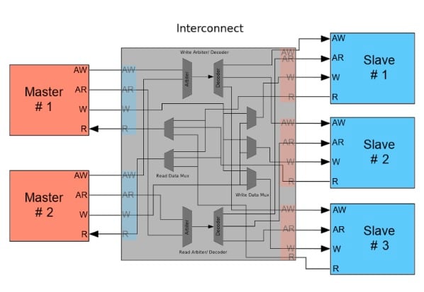
This is where AXI provides the most flexibility. Instead of prescribing how multi-master and multi-slave systems work, the AXI standard only defines the interfaces and leaves the rest up to the designer. If the system has multiple masters attempting to communicate with a single slave, then the AXI Interconnect may contain an arbiter that routes data between the master and slave interfaces. This arbiter could be implemented using simple priorities, a round-robin architecture, or whatever suits the designer's needs.
Systems that use multiple masters and multiple slaves could have interconnects containing arbiters, decoders, multiplexers, and whatever else is needed to successfully process transactions. This might include logic to translate between AXI3, AXI4, and AXI4-Lite protocols.
Additionally, interconnects can perform bus-width conversion, use data FIFOs, contain register slices to break timing paths, and even convert between two different clock domains.
Burst len, size, type:
The burst length for AXI3 is 1~16, for AXI4 is 1~256(INCR) and 1~16(other burst type)
Burstsize: the maximum number of bytes to transfer in each data transfer, or beat, in a burst.
If the AXI bus is wider than the burst size, the AXI interface must determine from the transfer address which byte of lanes of the data bus to use for each transfer. See Data read and write structure on axi spec.
The size of any transfer must not exceed the data bus width of either agent in the transaction.
Interesting history: Why a burst cannot cross a 4KB address boundary
Out of order:
Data from read transaction ARID values can arrive in any order
Interleave:
Read data of transaction with different ARID values can be interleaved
Write Interleaved: AXI3 support, but the first item of write data must be issued in the same order as the write address. AXI4 does not support interleave.
MIB RFC:
RFC2819 : Remote Network Monitoring Management Information Base
RFC2863: The Interfaces Group MIB
RFC3273: Remote Network Monitoring Management Information Base for High
RFC4836: Definitions of Managed Objects for IEEE 802.3 Medium Attachment Units (MAUs)
RFC3635: Definitions of Managed Objects for the Ethernet-like Interface Types
PFC MIB counter
Networking Protocols:
1. What is the exact difference between SGMII and 1000Base-X?
Unaligned Address:
TODO
AXI response
5. USB2.0
USB2 made simple(better and low level)
USB in a nutshell(introductory)
6. SPI
MIB RFC:
RFC2819 : Remote Network Monitoring Management Information Base
RFC2863: The Interfaces Group MIB
RFC3273: Remote Network Monitoring Management Information Base for High
RFC4836: Definitions of Managed Objects for IEEE 802.3 Medium Attachment Units (MAUs)
RFC3635: Definitions of Managed Objects for the Ethernet-like Interface Types
PFC MIB counter
Networking Protocols:
1. What is the exact difference between SGMII and 1000Base-X?
Subscribe to:
Comments (Atom)