1. The Protocol
Resolving address conflicts: https://embeddedartistry.com/blog/2021/08/02/resolving-i2c-address-conflicts/
1.1 Controller control the bus, in particular controls the SCL clock line to control the speed of transmissions
Peripherals cannot control the bus directly.
Pull-up resistors for pull up line to high. Resistor selection varies with devices on the bus, but a good rule of thumb is to start with 4.7kΩ resistor and adjust down if necessary. I2C is a fairly robust protocol, and can be used with short runs of wire (2-3m). For long runs, or systems with lots of devices, smaller resistors are better.
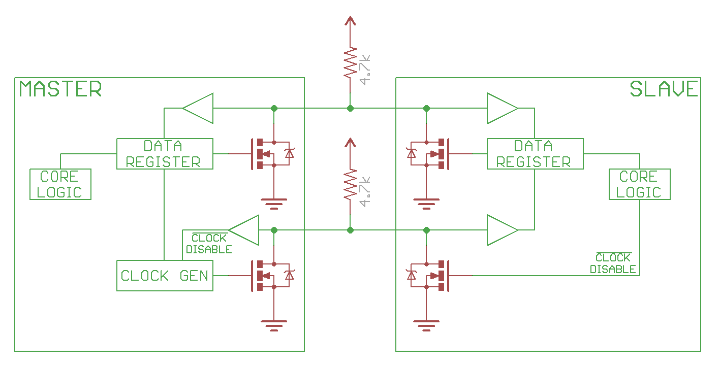
1.2 controller (master), peripheral(slave) use open drain drivers, to pull the line low, turn on the FET, to have the line high, just disconnect the FET (open drain), and the pull up resistor will pull line to high.
below image is from Sparkfun tutorials (sparkfun i2c tutorial)
1.3 speed
100kHz (Standard Mode)
400kHz (Fast Mode, Fm)
1MHz(Fast Mode Plus, Fm+)
3.4MHz(High-Speed Mode, Hs)
5MHz(Ultra Fast Mode, Ufm) - completely different bus, no pullup resistor, not common at all yet.
1.4 Start/Stop conditions
The only time the data line can change when the clock line is high is during the Start and Stop conditions.
Start marks the beginning of I2C transaction, bus must be idle, both SDA and SCL must be high. SDA goes low first, followed shortly by SCL.
Stop marks the end of I2C transaction. bus must be active, both SDA and SCL must be low. SCL goes high first, followed by SDA.
1.5 Sending Address and Data
Controller must send an address for every transaction. the address is to identify the peripheral that the controller is trying to talk to.
The address is 7bits, with one extra bit for Read(1)/Write(0).
Data is sampled at rising clock edge.
During regular transmissions, the the Controllers/Peripherals must wait until the clock line is low before changing the data line to set for the next bit to transmit.
data is always sent in unit of 8bits (1 Byte), transmitted most significant bit (MSB) first.
1.6. ACK/NACK
Each 8bits data/address must be followed by a ACK/NACK bit.
The side receiving the data needs to drive the ACK/NACK bit.
ACK bit is 0, NACK is 1.
when the controller is sending address, the NACK is set if no peripherals match that address.
when controller is writing, the peripheral send ACK if
when controller is reading, the controller send ACK if it wants to continue read data, and NACK to notify the peripheral to end the transaction.
1.7 Arbitration
arbitraion is automatic. Each controller is monitoring the line state, and the losing side will know it lost the arbitration once it trying to send a 1 but the line state is 1. It's non destructive, in that the winning side does not even know that there is a arbitration happened! that's the beauty of
1.8 Repeated Start Condition
sometimes controller end a transaction by sending another Start condition instead of a Stop condition. this is called Repeated Start Condition. this happens when controller wants to start a new transaction without letting go of the bus. Common example is when controller wants to switch from writing data to a peripheral to reading data from a peripheral.
1.9 10-bit Addressing
a specific 7-bit address value (7'b11110xx) denotes that the I2C is using 10-bit extended addressing scheme. the first two bits of the 10-bit address is in the last 2 bits of the 7-bit address value, and the remaining 8bits is sent as the following data byte. the read immediately after write is bit different, refer to Fig. 15 in the I2C spec.
1.10 Clock Streching
2. Arduino Software Application